이 게시물은 <킹 오브 네트워킹 (피터전)>을 공부한 내용을 바탕으로 작성됨.
하나의 스위치를 사용한 토폴로지
Bus Topology

스위치 1대를 이용할 때 버스 토폴로지는 위 네트워크처럼 구성된다. 물리적으로는 4개의 라우터 전부가 동시에 연결되어있는 것처럼 보이지만, 실제로는 인접한 라우터들끼리만 연결이 가능하도록 구성했다. 어떻게? VLAN을 이용.
인접한 interface끼리만 서로 같은 VLAN에 넣어주면 된다.
라우터에서 sub-interface를 설정할 때는 각 sub-interface 마다 별도의 VLAN을 지정해주어야 한다. 그래야 해당 VLAN에 속한 sub-interface들끼리 연결이 가능하기 때문. 그리고 그 sub-interface와 연결된 스위치의 port도 트렁크로 동작시켜야 한다.
그리고 이 경우에는 서로 한 다리 이상 건너 뛰면 연결이 불가능하다. 예를 들어 R1에서 R3, R4로는 연결할 수 없다. 서로 다른 VLAN에 존재하기 때문이다.
SW1(config)#vlan 12
SW1(config-vlan)#vlan 23
SW1(config-vlan)#vlan 34
SW1(config-vlan)#exit

SW1(config)#interface f0/1
SW1(config-if)#switchport mode access
SW1(config-if)#switchport access vlan 12
SW1(config-if)#exit

SW1(config)#interface range f0/2-4
SW1(config-if-range)#switchport mode trunk
Switch 설정은 위와 같다. 4개의 라우터 경로를 각각 논리적으로 분할하기 위해 VLAN을 총 3개 설정했고, VLAN 각각의 이름은 12, 23, 34이다. 또한 R1은 VLAN 12에 속하도록 했는데, 그렇다면 이와 연결되는 R2의 Gi 0/0.12도 VLAN 12에 속하도록 설정해야한다.
① R1

R1(config)#interface Gi 0/0
R1(config-if)#ip address 1.1.12.1 255.255.255.0
R1(config-if)#no shut


② R2

R2(config)#interface Gi0/0
R2(config-if)#no shut

R2(config)#interface Gi0/0.12
R2(config-subif)#encapsulation dot1Q 12
R2(config-subif)#ip address 1.1.12.2 255.255.255.0
R2(config-subif)#exit

R2(config)#interface gi0/0.23
R2(config-subif)#encapsulation dot1Q 23
R2(config-subif)#ip address 1.1.23.2 255.255.255.0


③ R3

R3(config)#interface gi 0/0
R3(config-if)#no shut

R3(config)#interface gi0/0.23
R3(config-subif)#encapsulation dot1Q 23
R3(config-subif)#ip address 1.1.23.3 255.255.255.0
R3(config-subif)#exit

R3(config)#interface gi0/0.34
R3(config-subif)#encapsulation dot1q 34
R3(config-subif)#ip address 1.1.34.3 255.255.255.0


④ R4

R4(config)#interface Gi0/0
R4(config-if)#no shut

R4(config)#interface Gi 0/0.34
R4(config-subif)#encapsulation dot1q 34
R4(config-subif)#ip address 1.1.34.4 255.255.255.0
위에서 R2,3,4는 Trunk로 설정해주었으므로 각각 interface에 사용될 트렁킹 방식을 dot1q로 지정해주었다.
R1#ping 1.1.12.2

Type escape sequence to abort.
Sending 5, 100-byte ICMP Echos to 1.1.12.2, timeout is 2 seconds:
.!!!!
Success rate is 80 percent (4/5), round-trip min/avg/max = 0/0/0 ms
R1에서 바로 옆 라우터인 R2(1.1.12.2)에 핑을 때린 결과이다. 잘 작동한다.
Ring Topology
SW1

SW1(config)#vlan 12
SW1(config-vlan)#vlan 24
SW1(config-vlan)#vlan 34
SW1(config-vlan)#vlan 13

SW1(config)#interface range f0/1-4
SW1(config-if-range)#switchport mode trunk
① R1

R1(config)#interface GigabitEthernet 0/1
R1(config-if)#no shut

R1(config)#interface gi 0/1.12
R1(config-subif)#encapsulation dot1q 12
R1(config-subif)#ip address 1.1.12.1 255.255.255.0
R1(config-subif)#exit

R1(config)#interface gi0/1.13
R1(config-subif)#encapsulation dot1q 13
R1(config-subif)#ip address 1.1.13.1 255.255.255.0


② R2

R2(config)#interface GigabitEthernet 0/1
R2(config-if)#no shut

R2(config)#interface GigabitEthernet 0/1.12
R2(config-subif)#encapsulation dot1q 12
R2(config-subif)#ip address 1.1.12.2 255.255.255.0
R2(config-subif)#exit

R2(config)#interface gigabitEthernet 0/1.24
R2(config-subif)#encapsulation dot1q 24
R2(config-subif)#ip address 1.1.24.2 255.255.255.0
이게 뭔말인가.. 이게 어째서 Ring 토폴로지인가.. 싶을 수 있다. VLAN을 이용하여 논리적으로 구성한 것이라 물리적인 형태는 Ring보다 Star에 가깝다. 하지만 각 라우터가 서로 이어지는 공간을 서로 다른 VLAN으로 설정하여 한 라우터에서 인접한 좌우 라우터로만 연결이 될 수 있게 구성하여, 실제 동작은 Ring 토폴로지다.
③ R3

R3(config)#interface Gi 0/1
R3(config-if)#no shut

R3(config)#interface Gi 0/1.13
R3(config-subif)#encapsulation dot1q 13
R3(config-subif)#ip address 1.1.13.3 255.255.255.0
R3(config-subif)#exit

R3(config)#interface Gi 0/1.34
R3(config-subif)#encapsulation dot1q 34
R3(config-subif)#ip address 1.1.34.3 255.255.255.0


④ R4

R4(config)#interface Gi 0/1
R4(config-if)#no shut

R4(config)#interface Gi 0/1.24
R4(config-subif)#encapsulation dot1q 24
R4(config-subif)#ip address 1.1.24.4 255.255.255.0
R4(config-subif)#exit

R4(config)#interface Gi 0/1.34
R4(config-subif)#encapsulation dot1q 34
R4(config-subif)#ip address 1.1.34.4 255.255.255.0
R1에서 R2, R3방향으로 핑을 때려본다. 단, R1이 속한 VLAN 12, VLAN 13 port에만 연결이 가능하다. R2의 VLAN 24 port와 R3의 VLAN 34 port와는 연결이 불가능하다.
R1#ping 1.1.12.2

Type escape sequence to abort.
Sending 5, 100-byte ICMP Echos to 1.1.12.2, timeout is 2 seconds:
.!!!!
Success rate is 80 percent (4/5), round-trip min/avg/max = 0/0/0 ms


R1#ping 1.1.13.3

Type escape sequence to abort.
Sending 5, 100-byte ICMP Echos to 1.1.13.3, timeout is 2 seconds:
.!!!!
Success rate is 80 percent (4/5), round-trip min/avg/max = 0/0/0 ms


R1#ping 1.1.34.3

Type escape sequence to abort.
Sending 5, 100-byte ICMP Echos to 1.1.34.3, timeout is 2 seconds:
.....
Success rate is 0 percent (0/5)

Star Topology

SW1(config)#vlan 12
SW1(config-vlan)#vlan 13
SW1(config-vlan)#vlan 14

SW1(config)#interface range f0/1-4
SW1(config-if-range)#switchport mode trunk
① R1

R1(config)#interface Gi 0/0
R1(config-if)#no shut

R1(config)#interface gi 0/0.12
R1(config-subif)#encapsulation dot1q 12
R1(config-subif)#ip address 1.1.12.1 255.255.255.0
R1(config-subif)#exit

R1(config)#interface Gi 0/0.13
R1(config-subif)#encapsulation dot1q 13
R1(config-subif)#ip address 1.1.13.1 255.255.255.0
R1(config-subif)#exit

R1(config)#interface gi 0/0.14
R1(config-subif)#encapsulation dot1q 14
R1(config-subif)#ip address 1.1.14.1 255.255.255.0


② R2

R2(config)#interface Gi 0/0
R2(config-if)#no shut

R2(config)#interface Gi 0/0.12
R2(config-subif)#encapsulation dot1q 12
R2(config-subif)#ip address 1.1.12.2 255.255.255.0
R3, R4도 알잘딱 설정해주면 된다.
R1#ping 1.1.12.2

Type escape sequence to abort.
Sending 5, 100-byte ICMP Echos to 1.1.12.2, timeout is 2 seconds:
.....
Success rate is 0 percent (0/5)

R1#ping 1.1.12.2

Type escape sequence to abort.
Sending 5, 100-byte ICMP Echos to 1.1.12.2, timeout is 2 seconds:
.!!!!
Success rate is 80 percent (4/5), round-trip min/avg/max = 0/0/1 ms

R1#ping 1.1.13.3

Type escape sequence to abort.
Sending 5, 100-byte ICMP Echos to 1.1.13.3, timeout is 2 seconds:
.!!!!
Success rate is 80 percent (4/5), round-trip min/avg/max = 0/0/1 ms

R1#ping 1.1.14.4

Type escape sequence to abort.
Sending 5, 100-byte ICMP Echos to 1.1.14.4, timeout is 2 seconds:
.!!!!
Success rate is 80 percent (4/5), round-trip min/avg/max = 0/0/2 ms
R1에서 R2, R3, R4에 전부 다 핑을 때려봤다. 아주 잘 작동한다.
R2#ping 1.1.14.4

Type escape sequence to abort.
Sending 5, 100-byte ICMP Echos to 1.1.14.4, timeout is 2 seconds:
.....
Success rate is 0 percent (0/5)
반면 R2에서 R4으로는 연결이 불가능하다.
Full mesh Topology
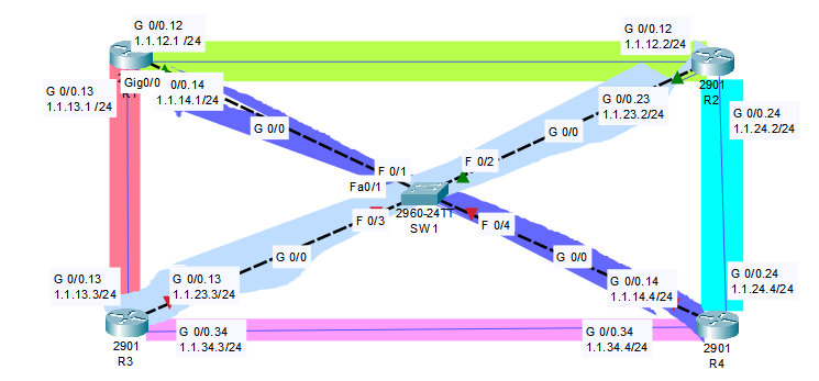
Full mesh는 모든 라우터가 직접 연결되어 있는 형태이다.
SW1(config)#vlan 12
SW1(config-vlan)#vlan 13
SW1(config-vlan)#vlan 14
SW1(config-vlan)#vlan 23
SW1(config-vlan)#vlan 24
SW1(config-vlan)#vlan 34
SW1(config-vlan)#exit
SW1(config)#interface range f0/1-4
SW1(config-if-range)#switchport mode trunk
R1(config)#interface Gi 0/0
R1(config-if)#no shut

R1(config)#interface G0/0.12
R1(config-subif)#encapsulation dot1q 12
R1(config-subif)#ip address 1.1.12.1 255.255.255.0
R1(config-subif)#exit

R1(config)#interface G0/0.13
R1(config-subif)#encapsulation dot1q 13
R1(config-subif)#ip address 1.1.13.1 255.255.255.0
R1(config-subif)#exit

R1(config)#interface G0/0.14
R1(config-subif)#encapsulation dot1q 14
R1(config-subif)#ip address 1.1.14.1 255.255.255.0
하 너무 귀찮아져서 이건 여기까지 하겠다.
위에서 구성한 토폴로지들이랑 모양만 다를 뿐 핵심은 동일하다.
- 연결하고 싶은 interface끼리만 동일한 VLAN에 넣어준다.
- Router들에서 물리적으로 연결된 cable은 단 하나(스위치로 향하는 것)이지만, 논리적인 sub-interface를 이용하여 서로를 연결하고 있다.
- 이 모든것은 "스위치"덕에 가능한 일이다. 스위치를 이용하여야 VLAN을 구성할 수 있는 것이다.
- Sub-interface, VLAN은 물리적으로는 보이지 않는 구조이지만 스위치가 알잘딱 VLAN이 있는 '것처럼' 메시지를 전달한다.
Hybrid Topology
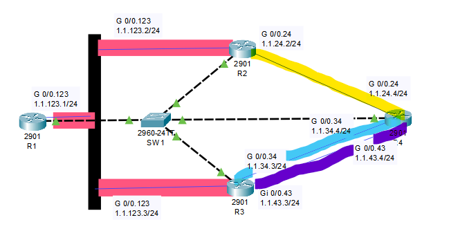
R 1,2,3 세 개가 서로 연결, 그리고 2-4 / 3-4 / 4-3으로 연결되어 있는 구조이다.
SW1(config)#vlan 123
SW1(config-vlan)#vlan 24
SW1(config-vlan)#vlan 34
SW1(config-vlan)#vlan 43
SW1(config-vlan)#exit
SW1(config)#interface range f0/1-4
SW1(config-if-range)#switchport mode trunk
① R1

R1(config)#interface Gi 0/0
R1(config-if)#no shut

R1(config)#interface Gi 0/0.123
R1(config-subif)#encapsulation dot1q 123
R1(config-subif)#ip address 1.1.123.1 255.255.255.0


② R2

R2(config)#interface Gi 0/0
R2(config-if)#no shut

R2(config)#interface Gi 0/0.123
R2(config-subif)#encapsulation dot1q 123
R2(config-subif)#ip address 1.1.123.2 255.255.255.0

R2(config)#interface Gi 0/0.24
R2(config-subif)#encapsulation dot1q 24
R2(config-subif)#ip address 1.1.24.2 255.255.255.0


③ R3

R3(config)#interface Gi 0/0
R3(config-if)#no shut

R3(config)#interface Gi0/0.123
R3(config-subif)#encapsulation dot1q 123
R3(config-subif)#ip address 1.1.123.3 255.255.255.0

R3(config)#interface Gi0/0.34
R3(config-subif)#encapsulation dot1q 34
R3(config-subif)#ip address 1.1.34.3 255.255.255.0

R3(config)#interface Gi 0/0.43
R3(config-subif)#encapsulation dot1q 43
R3(config-subif)#ip address 1.1.43.3 255.255.255.0


④ R4

Router(config)#host R4
R4(config)#interface Gi 0/0

R4(config)#interface Gi0/0.24
R4(config)#encapsulation dot1q 24
R4(config-subif)#ip address 1.1.24.4 255.255.255.0

R4(config)#interface Gi0/0.34
R4(config-subif)#encapsulation dot1q 34
R4(config-subif)#ip address 1.1.34.4 255.255.255.0

R4(config)#interface Gi0/0.43
R4(config-subif)#encapsulation dot1q 43
R4(config-subif)#ip address 1.1.43.4 255.255.255.0
두 대의 스위치를 사용한 토폴로지
Bus Topology

위 같은 토폴로지를 구성해보자. 1-2는 SW1을 통해, 2-3은 SW2를 통해, 3-4는 SW1을 통해 메시지를 교환하도록 VLAN을 구성한다.
즉 1-2 or 3-4에서 메시지 교환이 발생할 때는 SW1을 이용하고, 2-3에서 메시지 교환이 발생하면 SW2를 이용한다.
SW1(config)#vlan 12
SW1(config-vlan)#vlan 34
SW1(config-vlan)#exit
SW1(config)#interface range f0/1-2
SW1(config-if-range)#switchport access vlan 12
SW1(config-if-range)#exit
SW1(config)#interface range f0/3-4
SW1(config-if-range)#switchport access vlan 34
SW1(config-if-range)#exit
SW1에서 R1, R2와 연결되는 f0/1, f0/2를 VLAN 12로 설정하고, R3, R4와 연결되는 f0/3, f0/4를 VLAN 34로 설정한다.
SW2(config)#vlan 23
SW2(config-vlan)#exit
SW2(config)#interface range f0/2-3
SW2(config-if-range)#switchport access vlan 23
SW2에서는 R2, R3와 연결되는 f0/2, f0/3을 VLAN 23으로 설정한다.
① R1

R1(config)#interface g0/0
R1(config-if)#ip address 1.1.12.1 255.255.255.0
R1(config-if)#no shut


② R2

R2(config)#interface g0/0
R2(config-if)#ip address 1.1.12.2 255.255.255.0
R2(config-if)#no shut

R2(config)#interface g0/1
R2(config-if)#ip address 1.1.23.2 255.255.255.0
R2(config-if)#no shut


③ R3

R3(config)#interface g0/1
R3(config-if)#ip address 1.1.23.3 255.255.255.0
R3(config-if)#no shut
R3(config-if)#exit

R3(config)#interface g0/0
R3(config-if)#ip address 1.1.34.3 255.255.255.0
R3(config-if)#no shut
R3(config-if)#exit


④ R4

R4(config)#interface G0/0
R4(config-if)#ip address 1.1.34.4 255.255.255.0
R4(config-if)#no shut
내용 추가 예정!
'네트워크' 카테고리의 다른 글
| [네트워크] 32. 정적 경로 라우팅, 루프백 인터페이스, 디폴트 루트 (1) | 2024.01.14 |
|---|---|
| [네트워크] 31. 라우팅 프로토콜 (0) | 2024.01.14 |
| [네트워크] 29. VLAN, 트렁킹, VTP (0) | 2024.01.11 |
| [네트워크] 28. ARP, 트랜스패런트 브리징 (1) | 2024.01.11 |
| [네트워크] 27. 텔넷, SSH, 이더넷 프레임, L123 장비들 (0) | 2024.01.10 |


